Kitchen Ecology Unit

Ecology Unit for Commercial & Industrial Kitchens

Advanced Filtration Solution for Exhaust Ventilation Systems

With the growing global emphasis on environmental responsibility and the collective goal to reduce emissions and pollution, the management of cooking fumes from commercial kitchens has become crucial. An Ecology Unit plays a key role in ensuring cleaner air by effectively filtering grease, smoke, and gaseous pollutants generated during commercial cooking processes.


Purpose of the Ecology Unit:

The Ecology Unit acts as a secondary filtration stage, working in conjunction with a properly selected kitchen hood system. While the hood captures primary grease and smoke at the source, the Ecology Unit provides enhanced filtration to meet air quality and environmental standards.

Multi-Stage Filtration Process:

A typical Ecology Unit features 4 to 5 stages of advanced filtration to ensure high removal efficiency and long-term performance. The system is designed for commercial and industrial kitchen exhaust ventilation, handling varying pollutant loads depending on the cuisine type and cooking intensity.

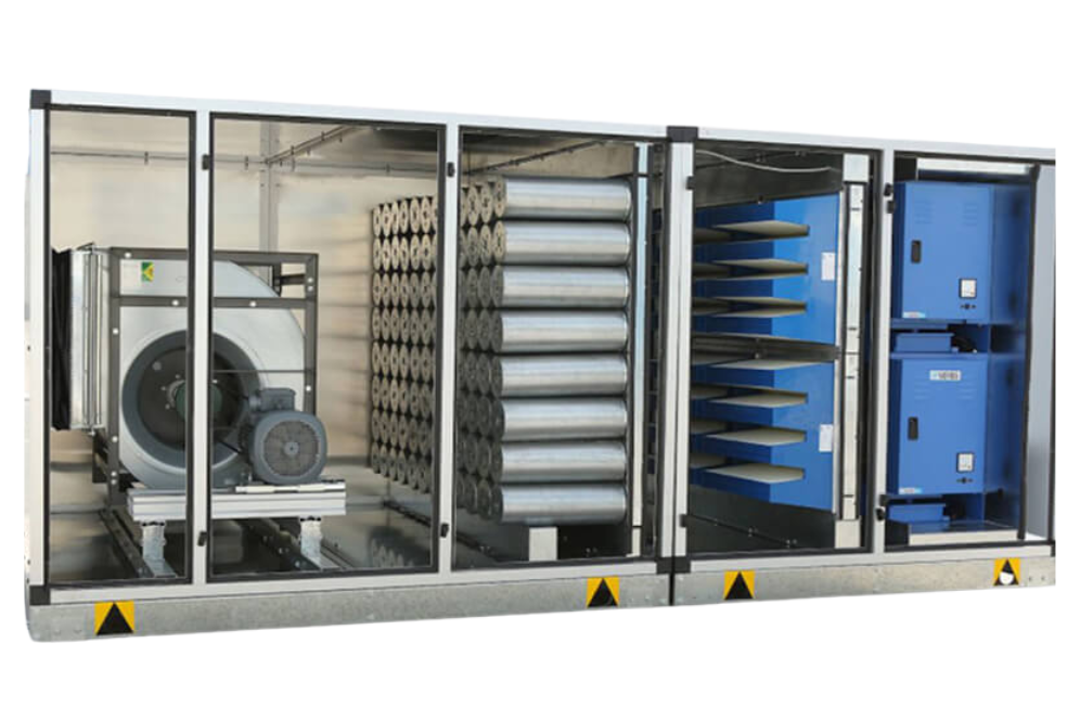
Key Components of a Kitchen Ecology Unit

  1. Pre-Filtration System
    Grease Filter
    Purpose: Captures large oil and grease particles directly from cooking exhaust.
    Type: Stainless steel or aluminum baffle filters or mesh filters.
    Function: Protects downstream filters by removing heavy grease and mist.

  2. Electrostatic Precipitator (ESP)
    Purpose: Removes fine grease, smoke, and mist particles.
    Components:
    Ionizing Section: Electrifies airborne particles.
    Collector Plates: Capture and hold charged particles.
    Benefit: Highly efficient in reducing smoke and micro-particles.

  3. Bag Filter (Fine Dust Filter)
    Purpose: Removes fine particulates not captured by the ESP.
    Material: Fiberglass media or synthetic fabric.
    Configuration: Multi-pocket/bag design for high dust holding capacity.

  4. Gas Phase Filtration System (Odor & Gas Control)
    V-Type Mini Pleated Carbon Filter
    Media: Premium granular activated carbon.
    Purpose: Adsorbs odors, VOCs, and chemical fumes.
    Design: V-type structure for maximum surface area.
    Canister-Type Carbon Filter
    Structure: Cylindrical canisters filled with granular activated carbon.
    Frame: Leak-proof holding system to ensure complete airflow through the carbon media.
    Cassette-Type Carbon Filter
    Design: Modular, easy-to-replace flat filter cassettes filled with activated carbon.
    Honeycomb Filter
    Structure: Honeycomb configuration for uniform airflow and odor control.
    Media: High-adsorption carbon media embedded in a honeycomb grid.

  5. After Filter (Final Polishing Filter)
    Purpose: Captures carbon dust or any remaining fine particulates.
    Placement: After the carbon filtration stages.

  6. Centrifugal Fan & Motor Assembly
    Function: Maintains proper airflow through all filtration stages.
    Features: High static pressure capability, efficient motor, optional silencers for noise reduction.

  7. Control Panel & Electrical System
    Purpose: Operates and monitors the system.
    Functions:
    Fan control
    ESP voltage regulation
    Filter status indicators (optional)
    Safety interlocks

  8. Access Doors & Service Panels
    Purpose: Easy access for filter replacement, cleaning, and maintenance.
    Design: Tool-free or hinged doors with gaskets for airtight sealing.

  9. Structural Frame & Housing
    Material: Galvanized steel or stainless steel (optional for hygiene-critical areas).

    Features:
    Robust construction to withstand kitchen conditions.
    Corrosion-resistant coating or stainless-steel options.
Summary of Components
Component Function
Grease Filter
Removes oil and grease mist
Electrostatic Precipitator (ESP)
Removes smoke and fine mist
Bag Filter
Removes fine dust and particulates
Carbon Filters (V-type, Canister, Cassette, Honeycomb)
Removes odors and gases
After Filter
Captures carbon dust
Centrifugal Fan & Motor
Ensures airflow
Control Panel
Manages system operation
Access Doors
Maintenance access
Housing & Frame
Structural integrity and safety
Optional: UV Lamp / Odor Sensor
Microbial and odor control (optional)

Main Components of a Process Chiller

An Industrial Process Chiller is made up of several essential components that work together to regulate temperature and ensure smooth operation. Each part plays a crucial role in the refrigeration cycle:

  1. Compressor:
    This is the heart of the chiller. It compresses the refrigerant gas, increasing its pressure and temperature so it can move through the system efficiently. Types of compressors include scroll, screw, reciprocating, and centrifugal, depending on the chiller’s capacity and design.
  2. Evaporator:
    The evaporator is where the process fluid (such as water or glycol) passes through and loses its heat to the refrigerant. This is where heat absorption occurs, and the refrigerant turns into a gas.
  3. Condenser:
    After compression, the hot refrigerant gas flows into the condenser. In this component, the heat is removed either by air (air-cooled) or water (water-cooled), and the refrigerant changes back into a liquid.
  4. Expansion Valve:
    The expansion valve regulates the flow of refrigerant into the evaporator. It reduces the pressure and temperature of the liquid refrigerant before it re-enters the evaporator to absorb more heat.
  5. Process Pump & Reservoir:
    A circulation pump pushes the cooled fluid to the process and brings the warmed fluid back to the chiller. The reservoir holds the process fluid and acts as a buffer to handle thermal loads.
  6. Control System:
    Modern chillers come with advanced control panels and sensors that monitor and regulate temperatures, flow rates, pressures, and operating parameters for safety, efficiency, and precision.
    Together, these components form a reliable and energy-efficient system that keeps industrial operations stable, regardless of heat-generating activities within the facility.
Subscription Form