Vacuum Degassers

Vacuum degassers are installed in a bypass in the main flow of heating and cooling systems. Part of the system fluid is temporarily placed in a vacuum. Gases dissolved in the fluid are released, separated and removed from the system. Reintroducing the degassed fluid into the system allows it to absorb further free air pockets from the circuit. Air-free installation fluid ensures optimum system performance, and also greatly reduces commissioning times. Besides realising optimised system efficiency, our standard models save extra energy thanks to the integrated Smart Switch. This device ensures that the degasser is only operational when necessary.

The main purpose of the vacuum deaerator is to release the dissolved gases circulating in closed-circuit heating and cooling systems and to discharge them from the system.

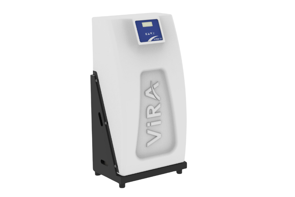
Inventure offers Vacuum degasser from Vira – Turkey. ViraDeg vacuum degasser is connected to the system as a by-pass and after pressurizing the water it has taken from the system, it applies a vacuum, allowing dissolved gases to be released in the water. The released gases are discharged from the system using airvents. 

Vacuum degassing is the technique of removing dissolved gas from a liquid solution by lowering the pressure inside a vessel containing the solution. Vacuum degassing is the process of removing dissolved gas from a liquid solution by lowering the pressure inside a vessel containing the solution. The reduced pressure inside the vessel causes the gas to become less soluble and separate from the liquefied material. After vacuum degassing is complete, the gas is removed from the vessel and the pressure returns to normal.

Benefits

  1. Removes all gases, including free air, microbubbles, and dissolved gases from the system, ensuring complete and effective degassing for stable and efficient operation.
  2. The absorptive fluid further supports the process by capturing and eliminating trapped gas bubbles that remain in the system, improving overall air separation performance.
  3. Designed for easy and quick installation, which significantly reduces commissioning time and simplifies system handover, saving both effort and operational costs.
  4. Operates in an energy-efficient manner while still achieving the lowest possible gas concentration levels, helping to improve system efficiency and reduce power consumption.
  5. Maintains optimal gas concentration levels with the help of SmartSwitch technology, which intelligently controls and optimizes system performance.
  6. Enables degassed (re)filling of the system and maintains sustained and stable pressure conditions, ensuring reliable and long-term operation.
  7. Provides early warning alerts before (re)filling becomes excessive, allowing preventive action and protecting the system from overfilling or pressure-related issues.
  8. Available in an extensive product range that suits a wide variety of system sizes, capacities, and application requirements.
  9. Fully compatible and capable of working seamlessly with all common types of expansion systems, ensuring easy integration into existing installations.

Main Components of a Process Chiller

An Industrial Process Chiller is made up of several essential components that work together to regulate temperature and ensure smooth operation. Each part plays a crucial role in the refrigeration cycle:

  1. Compressor:
    This is the heart of the chiller. It compresses the refrigerant gas, increasing its pressure and temperature so it can move through the system efficiently. Types of compressors include scroll, screw, reciprocating, and centrifugal, depending on the chiller’s capacity and design.
  2. Evaporator:
    The evaporator is where the process fluid (such as water or glycol) passes through and loses its heat to the refrigerant. This is where heat absorption occurs, and the refrigerant turns into a gas.
  3. Condenser:
    After compression, the hot refrigerant gas flows into the condenser. In this component, the heat is removed either by air (air-cooled) or water (water-cooled), and the refrigerant changes back into a liquid.
  4. Expansion Valve:
    The expansion valve regulates the flow of refrigerant into the evaporator. It reduces the pressure and temperature of the liquid refrigerant before it re-enters the evaporator to absorb more heat.
  5. Process Pump & Reservoir:
    A circulation pump pushes the cooled fluid to the process and brings the warmed fluid back to the chiller. The reservoir holds the process fluid and acts as a buffer to handle thermal loads.
  6. Control System:
    Modern chillers come with advanced control panels and sensors that monitor and regulate temperatures, flow rates, pressures, and operating parameters for safety, efficiency, and precision.
    Together, these components form a reliable and energy-efficient system that keeps industrial operations stable, regardless of heat-generating activities within the facility.
Subscription Form