A Buffer Tank is an essential component in chilled water or hot water HVAC systems, designed to increase system fluid volume, stabilize temperatures, and reduce equipment cycling. Its construction is engineered for durability, thermal efficiency, and long-term system performance.
1. Outer Shell (Tank Body)
Material: Carbon Steel is the most commonly used material for the outer shell due to its high strength, durability, and ability to withstand internal pressure and temperature variations in HVAC and industrial fluid systems. It also provides good weldability and long service life when properly coated or painted for corrosion protection.
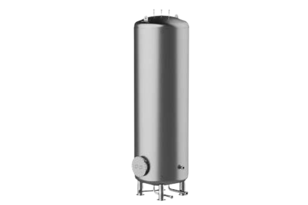
Shape: The tank is manufactured in a cylindrical shape, which offers uniform stress distribution and structural stability under pressure. Depending on site conditions and space availability, the tank can be installed in either a horizontal or vertical orientation. The selection of orientation is based on layout, maintenance access, and piping arrangement.
Thickness: The shell thickness is designed and calculated according to ASME standards or other applicable pressure vessel design codes to ensure safe operation. The thickness varies with operating pressure and temperature. For standard applications, the pressure rating is typically in the range of 6–10 bar, while higher thickness is provided for systems requiring higher pressure ratings.
2. Internal Volume
Capacity: The storage capacity of the tank ranges from as low as 100 liters for small systems to several thousand liters for large commercial or industrial installations. The exact volume is selected based on system load, flow rate, and buffering requirements.
Purpose: The internal volume holds additional system fluid, increasing the overall thermal mass of the system. This helps in stabilizing temperature fluctuations, reducing short cycling of chillers or boilers, and improving overall system efficiency and operational stability.
3. Insulation
Material: Common insulation materials used include Polyurethane Foam (PUF), Rockwool, and Fiberglass. These materials are selected for their low thermal conductivity, fire resistance (in case of Rockwool), and long-term thermal performance.
Purpose: The insulation layer minimizes heat loss in hot water or heating systems and prevents unwanted heat gain in chilled water systems. This maintains desired fluid temperature, improves energy efficiency, and reduces load on heating or cooling equipment.
Thickness: The insulation thickness typically ranges from 25 mm to 100 mm, depending on the operating temperature, ambient conditions, and energy conservation requirements of the application.
4. Inlet & Outlet Connections
Pipe Connections: The inlet and outlet nozzles are positioned at strategically calculated locations to ensure proper flow distribution, effective mixing of fluid, and correct hydraulic balance within the tank. These connections are usually provided as threaded or flanged types, depending on pipe size, pressure class, and maintenance requirements.
Connection Types: Primary Loop Connection – Connects the tank to the chiller or boiler circuit, allowing thermal energy exchange and flow stabilization.
Secondary Loop Connection – Supplies conditioned water to the distribution system serving air handling units, fan coil units, or process loads.
5. Drain Valve
Location: A drain valve is installed at the lowest point of the tank to allow complete removal of fluid during shutdown, cleaning, or maintenance operations. This ensures easy servicing and prevents sediment accumulation.
6. Air Vent / Air Release Port
Purpose: The air vent removes trapped air during initial filling and normal operation, preventing air pockets that can cause flow obstruction, noise, corrosion, and loss of heat transfer efficiency.
Type: The vent may be a manual type for periodic air bleeding or an automatic air release valve for continuous removal of entrapped air.
7. Temperature Sensor Ports / Thermowells
Purpose: These ports are provided for installing temperature sensors or thermowells, enabling continuous monitoring and control of system temperature through building management or automation systems.
Placement: Sensors are generally located at both the top and bottom of the tank to observe temperature stratification and verify proper thermal layering and mixing.
8. Mounting Supports
Vertical Tanks: Vertical models are equipped with support legs or a base plate to ensure firm and level floor mounting, allowing safe load transfer to the foundation.
Horizontal Tanks: Mounted on saddles or cradles for stability.