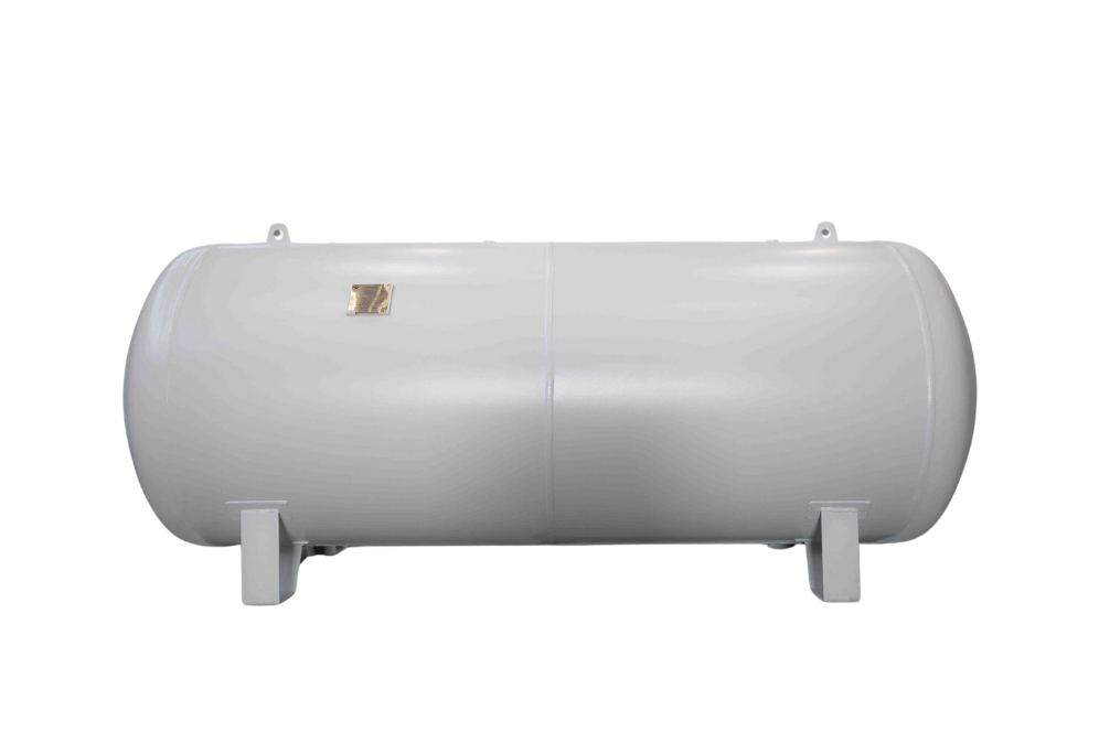
1. Outer Vessel
Shape: The outer shell is typically manufactured in a cylindrical or spherical shape, as these geometries provide uniform stress distribution under internal pressure and ensure structural stability during operation. The selected shape helps the vessel withstand repeated pressure fluctuations without deformation.
Material: Carbon Steel is the most commonly used material due to its high strength, pressure-handling capability, and long service life. It is suitable for heating, cooling, and water systems operating under varying temperature and pressure conditions.
Finish: Internal Finish: In certain models, especially those used for potable water or corrosive environments, the internal surface is provided with a corrosion-resistant lining to prevent contamination and extend the service life of the vessel.
External Finish: The external surface is protected with durable coatings such as powder coating or epoxy paint, which safeguard the vessel against rust, moisture, and environmental corrosion, ensuring long-term outdoor or indoor reliability.
2. Internal Construction
Flexible Membrane (Diaphragm or Bladder)
Purpose: The flexible membrane separates the fluid chamber from the gas chamber, preventing direct contact between the system fluid and the pressurized gas. This separation avoids gas absorption into the liquid and maintains stable system pressure.
Materials: EPDM (Ethylene Propylene Diene Monomer): Commonly used in heating and HVAC systems due to its excellent temperature resistance, elasticity, and compatibility with water and glycol mixtures.
Butyl Rubber: Used in high-performance and potable water applications because of its superior gas retention properties, flexibility, and compliance with drinking water standards.
Types:
Diaphragm-Type: In this design, the membrane is fixed to the inner wall of the tank, forming two distinct chambers for gas and fluid. The construction is relatively simple and robust, making it suitable for standard heating and cooling systems.
Bladder-Type: In this design, a balloon-like bladder fully contains the system fluid. The fluid remains completely isolated from the steel tank wall, which significantly reduces corrosion risk. In many models, the bladder is replaceable, allowing easier maintenance and longer service life.
3. Gas Chamber
Pre-Charged with Air or Inert Gas (e.g., Nitrogen): The gas chamber is factory filled with compressed air or nitrogen, which acts as a compressible cushion. As the system fluid expands due to temperature rise, the gas compresses and absorbs the expansion volume, maintaining pressure balance.
Pressure Setting: The vessel is pre-charged at the factory to a pressure value that typically matches the static pressure of the system. The pressure can be checked and adjusted through a Schrader valve (air valve) provided at the top of the vessel, allowing precise commissioning and maintenance.
4. Fluid Chamber
Connection: The fluid chamber is fitted with an inlet and outlet connection, generally located at the bottom or side of the vessel, for direct integration with the system’s piping network.
Function: During system operation, the expanding fluid enters the vessel and occupies the fluid chamber. This expansion displaces the membrane and compresses the gas in the gas chamber, thereby transferring pressure and stabilizing the entire system..